Introduction
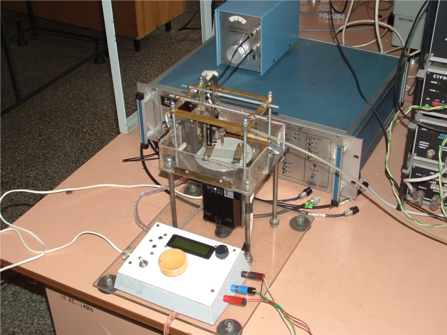
It was my diploma project. I decided to build a spin-coater because of few reasons. Firstly because it required innovative and creative thinking skills. Second reason was the manual work: I had to not only design but also build machine that would work. That wasn’t an easy task…
The goal was to use recycled materials/parts and build spin-coater: machine to produce thin polimer layers. Using recycled materials had two main reasons. First – price: spin coater can cost few tousand bucks (check google!). Second – environment: it was good (for mother earth) fun (for me) to build something out of trash. I used about 70% recycled mechanical/electronic parts in this project.
What is spin-coater?
Well, in a nutshell it is machine that uses centrifugal force to produce thin layers,
in example thin polymer films. What for? In past decades there was a rapid growth of
polymers usage. Many new technologies are based on polymer, because it conducts
current, it is plastic, corrosion proof and relatively cheap.
You can find
thin polymer layers in light sensors, thermometers (and other medical equipment),
millitary technologies (anti-radar paints) and many others.
Just a bit of theory
In theory, spin coating process is very simple. As you probably can guess, it has
something in common with spinning around and covering something. That’s true.
Spin coater uses centrifugal force, surface tension and evaporation of the liquid
polymer solution to get on a spinning disc very thin films (few micrometers) of the
polymer. Firstly, you need to put one drop of polymer on static disc. Next, you need
to speed up the disc to some high rotational speed (let’s say the higher speed
– the thinner layer). Then, at a high, permanent speed, solvent from solution
must evaporate. As a final efect you will get thin polymer film. By controlling
rotational speed you can also controll thinness of the layer.
In practice it
is not so simple. Thinness also depends on many factors: time of the spinning, the
way how you put polymer on disc, smoothness of the disc and many others. Let’s
check how the process looks like:
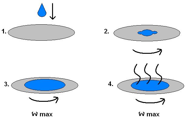
1. Polymer deposition on the disc
It is the first sequence of the
process, it provides liquid polymer on disc surface. I used a syringe as a
dispenser. For higher precission, it was controlled by stepper motor.
2. Speed-up
Second sequence of the process, in which liquid polymer
spreads around the disc because of the disc rotation (and centrifugal force). After
that, disc speeds-up to almost maximum rotational speed so that expected thinness is
almost final. In this sequence speed is about 1500 to 3000 rpm’s. It can take
few second or few minutes, depending on what polymer we use.
3. Making layer more flat
In third sequence thinness gets its maximum
value. The surplus of the liquid is thrown away from disk by centrifugal force.
4. Evaporation
Last sequence of the process. Liquid polymer is
coagulating, when solvent evaporates.
Designing and making spin-coater
Disc driver
I started work on machine from choosing proper electric
motor to speed up the disc. Because of costs I decided to use commutator motor with
permanent magnet (from old sewing machine). It has 90 W of power with 4500
rpm’s. Good enough. Of course better option would be small, brushless motor
from HDD (7k rpm’s) but controll process of such device was too complicated
for this project. I controlled the speed of commutator motor by dedicated module
based on triac.
Stepper motor
Second motor that I used in project was a stepper motor
from old FDD drive (5,25″). It was responsible for precise movements of
dispenser with liquid polymer.
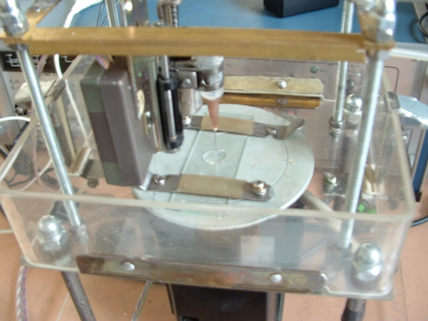
Liquid polymer dispenser
Next stage of the design was to create
something that would put drop of polymer on the disc. Because stepper motor
wouldn’t move some heavy device, I implemented medical syringe with needle for
that.
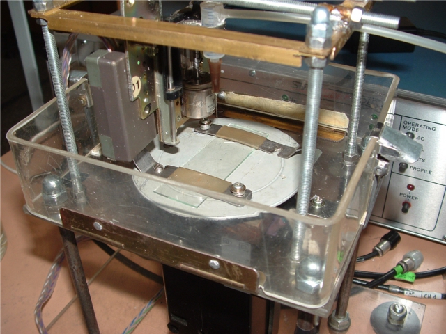
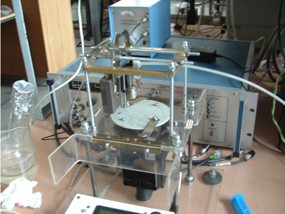
Disc and sample glass fixing system
I had a little trouble fixing the
glass sample to disc. It would had to be strong enough to keep sample on disc when
it speeds up to few k rpm’s, and gentle enough to not break the glass.
Moreover fixing system had to be easy enough to put/take sample to/from disc. I used
two metal plates as a fixing system. I was forced to put plexiglass shields around
the disc, just in case metal plates would be dropped at higher speed.
Frame construction
I build frame for my machine using plexiglass (light
and easy to form after heating) and cooper (easy to solder). That is why
construction was light and heavy-duty. Because of motor, whole machine got much
vibrations. I reduced them adding rubber silent-blocks under frame construction.
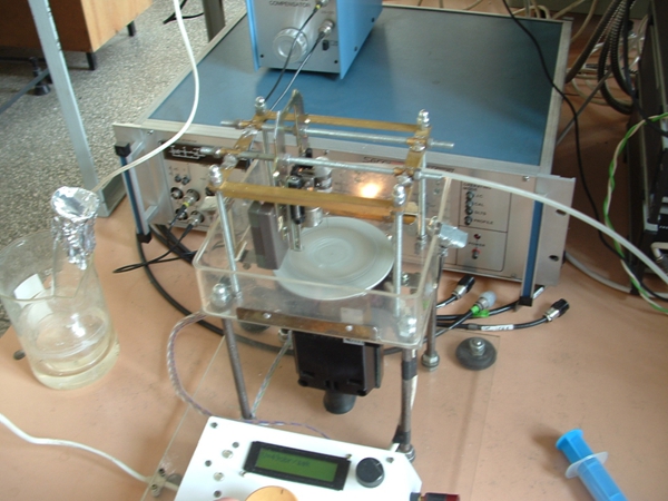
Desktop
Logic of the system was based on ATmega8 microcontroller. It
managed LCD display (HD44780 Hitachi) and stepper motor.
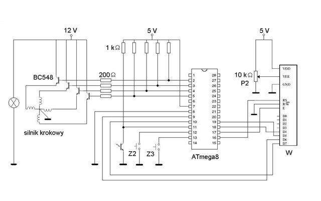
LCD and potentiometers (one for controlling brightness of LCD, second for controlling speed of the disc) was placed on desktop. Having all buttons on white piece of plastic was a good choice. My machine got a little bit of design beauty:)
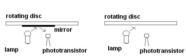
Tachometer
Spin coating process depends on rotational speed, so I needed
to check how fast disc is rotating at the moment. I implemented simple mechanism
with mirror, phototransistor and light bulb. I put small mirror under the disc. At
the time when light from bulb reaches the mirror, phototransistor conducts current.
In this way microprocessor caunted electrical impulses per minutes – which are
of course rounds per minutes. Final value of the speed was visible on LCD display
(displayed with 3 s frequency).
Summary
I had a great time working on spin-coater. I’ve compleated it in 2006. By that time, it was my first bigger experience with microcontrollers. There are some things I could’ve done better, but spin-coater worked and that was most important in the project!